
Hardware and software · Rack Technology
Simulyzer-RT
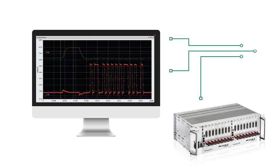
A powerful platform for sensor testing, data acquisition and simulation – with configurable chassis for multichannel test setups.
- Modular: Combine CPU, measurement and interface cards to suit your setup
- Synchronized: Coordinate time stamps across peripheral cards
- Connected: Gigabit Ethernet, ANSI-C API and .NET API
Software
Software & integration
Tools for configuration, custom applications and continuous sensor testing.
Included
ANSI-C API
Interface for integrating Simulyzer-RT into your own applications.
Included
.NET API
Integration with applications based on Microsoft .NET.
Included
Config Tool
Application for configuring the Simulyzer-RT system.
Optional
Signal Monitoring API
Extension for signal monitoring within your test and analysis applications.
Optional
Endurance application
Software for sensor endurance tests.
Technical data
System and chassis
Chassis, CPU and peripheral cards are selected to suit the interfaces, channel count and measurement task.
- Network
- 1 Gigabit Ethernet
- Card format
- 160 × 100 mm (Eurocard format)
- Peripheral slots
- 2 / 8 / 11 / 16, depending on chassis; further options on request
- Data acquisition
- Synchronized peripheral-card time stamps; recording locally or via a host PC
- Power supply
- Chassis-dependent: compact chassis with external 12 V DC supply; mains connection for configurations with a power supply
- Host compatibility
- Windows 7, 10 and 11; Microsoft .NET Framework 2.0; Linux via API, without GUI
- Data export
- CSV files (Excel) and TDMS files (NI)
- Operating modes
- Dependent on peripheral card and firmware; see the corresponding data sheet
Four chassis configurations
Peripheral slots
Compact chassis
1+2
External 12 V DC supply
Art. no. 20.1001
Peripheral slots
Standard chassis
1+8
300 W
Art. no. 20.1002
Peripheral slots
Double chassis
(1+7) + (1+4)
300 W
Art. no. 20.1003
Peripheral slots
Double chassis
(1+8) + (1+8)
500 W
Art. no. 20.1004
Configurations identify CPU and peripheral cards. The usable configuration depends on the CPU, backplane and power requirements.
Modular architecture
Cards at a glance
Central control, sensor interfaces and analog measurements in one system. Select the functions required by your test setup.
Central control
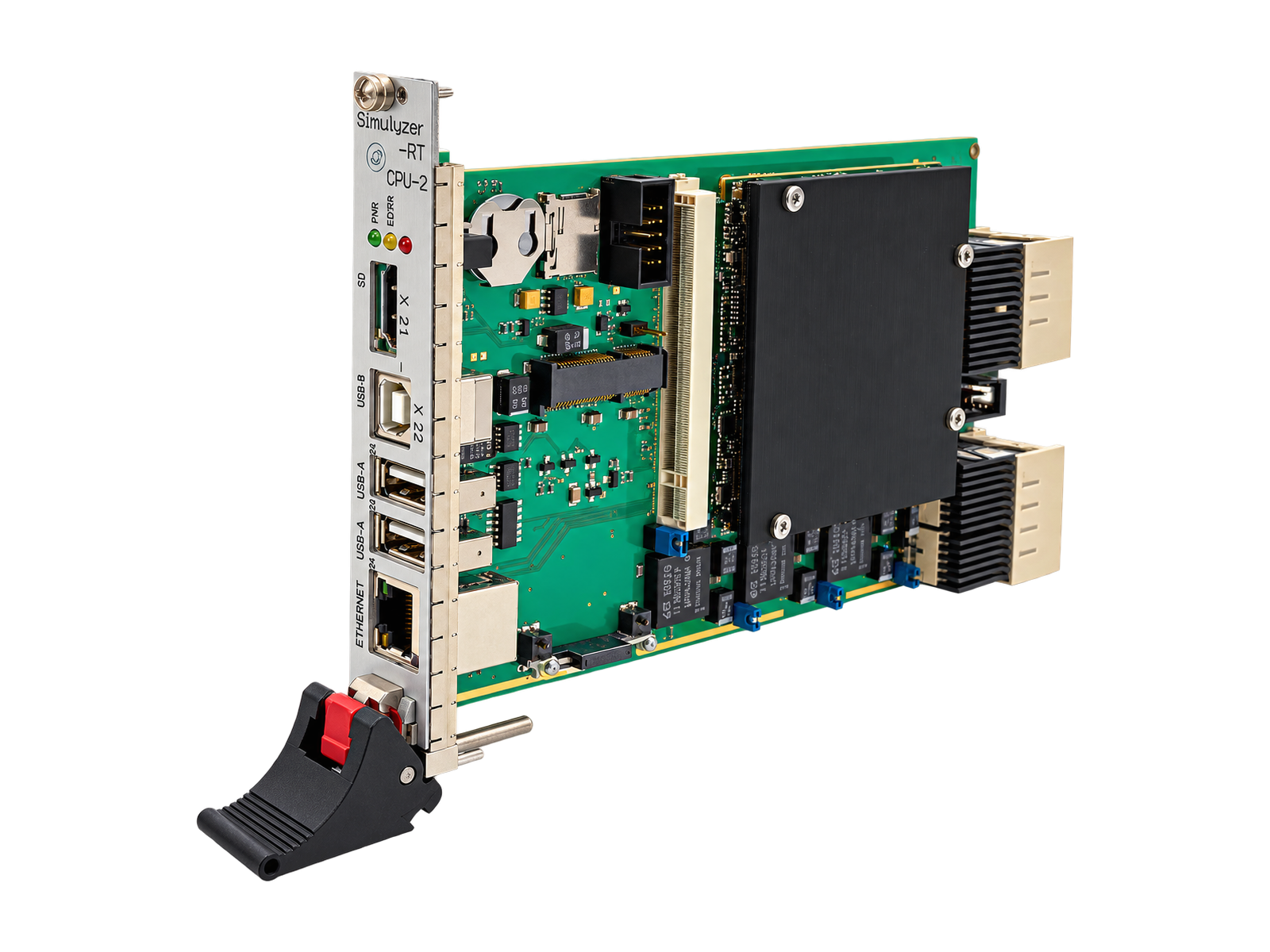
CPU-2
The CPU-2 connects peripheral cards to the operating system, mass storage, network and USB interfaces.
- CPU-2: article 20.2001
- Windows DLL/API included
- Select the CPU and peripheral configuration together

SPI · SPMI · I2X · SENT
DIO-2
48 digital I/Os for different interfaces. The DIO-2 supports SPI, SPMI, I2X or SENT depending on the installed firmware.
- Change protocols by reflashing the same card
- SPI configuration: e.g. four interfaces with four chip selects each
- Article 20.3004

SPI · SPMI · I2X · SENT · Low voltage
DIO-2 LV
The low-voltage version of the DIO-2 with 48 digital I/Os for 0.65–3.6 V. SPI, SPMI, I2X or SENT are provided by the corresponding firmware.
- Change protocols by reflashing the same card
- SPI configuration: e.g. four interfaces with four chip selects each
- Article 20.3005

Analog data acquisition
ADC
Acquire analog voltages on up to eight channels, continuously or using a trigger.
- Up to 120 MS/s on up to eight channels
- Input range −10 to +10 V; 16-bit resolution
- SMA connectors and configuration via API

PSI5
PSI5-ECU-1
Supply PSI5 sensors and acquire their communication in ECU or passive mode.
- Eight PSI5 interfaces
- Sensor supply 4–20 V; current measurement up to 120 mA, 14 bit
- PSI5 baud rates up to 250 kbit/s

Supply & measurement
PWR-ANA-1
Combine sensor supply and analog measurement to power and monitor eight sensors.
- Two adjustable supply voltages: 2–20 V, 1 A
- Measurement of supply voltages and sensor currents
- Three additional analog inputs per sensor, 24 in total

CAN / CAN-FD
CAN-2
Integrate CAN communication into the test setup via eight interfaces.
- Eight channels with galvanic isolation
- CAN up to 1 Mbit/s; CAN-FD up to 4 Mbit/s
- Adjustable sensor supply: 2–20 V
Additional interfaces and functions
PT100
PT100 card
An additional card option for your Simulyzer-RT system. Contact us to discuss its configuration and applications.
- Article 20.5007
In development · not yet available
Multisim
Planned expansion for sensor simulation via PSI5 or DSI3. Multisim is currently in development and is not yet available.
Applications and system integration
From sensor development to the test bench
Acquire, archive and simulate using a card combination matched to the measurement task.
Sensor characterization
Measure sensors, evaluate their behavior and perform adjustment tasks. Analog measurements and sensor interfaces can be combined within the system.
Endurance and EMC measurements
Acquire sensor communication over extended test sequences and archive measurement data. The setup is matched to the sensors and test environment.
ECU testing and production
Simulate sensor data to test ECUs and ECU algorithms. End-of-line sensor programming is another application area.
Knowledge & support
Documentation and data sheets
Documents organized by system, peripherals and documented variants.
System and chassis
Measurement and interface cards
Selection and integration
Documents for earlier variants and additional versions
For existing systems: CPU-1 and CPU-i3 are distinct variants. Their specifications do not automatically apply to CPU-2.
Each data sheet describes a specific hardware and document version. We can help match the documentation to your CPU, chassis and card configuration.
Ordering information
Article numbers
Chassis and cards with their configurations for your enquiry.
Chassis
| Art. no. | Product | Description |
|---|---|---|
| 20.1001 | Simulyzer-RT Compact chassis 1+2 | For one CPU card and two peripheral cards. |
| 20.1002 | Simulyzer-RT Standard chassis 1+8 | 300 W power supply; configuration with (1+8) cards. |
| 20.1003 | Simulyzer-RT Double chassis · 300 W | 300 W power supply; configuration with (1+7) + (1+4) cards. |
| 20.1004 | Simulyzer-RT Double chassis · 500 W | 500 W power supply; configuration with (1+8) + (1+8) cards. |
CPU cards
| Art. no. | Product | Description |
|---|---|---|
| 20.2001 | Simulyzer-RT CPU-2 | CPU card including Windows DLL/API. |
Peripheral cards
| Art. no. | Product | Description |
|---|---|---|
| 20.3004 | Simulyzer-RT DIO-2 | 48 digital I/Os; SPI, SPMI, I2X or SENT depending on firmware. Protocol changes by reflashing. SPI configuration: 4×4. |
| 20.3005 | Simulyzer-RT DIO-2 LV | 48 digital I/Os; SPI, SPMI, I2X or SENT depending on firmware. Protocol changes by reflashing. SPI configuration: 4×4; low voltage 0.65–3.6 V. |
| 20.4002 | Simulyzer-RT PSI5-ECU-1 · 8 interfaces | Peripheral card with eight PSI5 interfaces; ECU or passive mode. |
| 20.5001 | Simulyzer-RT PWR-ANA-1 | Power/analog peripheral card. |
| 20.5004 | Simulyzer-RT CAN-2 | Eight-channel CAN peripheral card. |
| 20.5006 | Simulyzer-RT ADC | Eight analog inputs. |
| 20.5007 | Simulyzer-RT PT100 | Simulyzer-RT PT100 card. |
Various adapters and software licenses are available on request. We can advise you on the appropriate DIO-2 firmware for SPI, SPMI, I2X or SENT.
Which cards does your test setup need?
Tell us about your interfaces, channel count and measurement task. Together, we will select a suitable combination of chassis, CPU, peripheral cards and software.
Discuss your project with us →