The communication from ECU to sensor occurs by modulation of the supply voltage.
In all synchronous working modes a synchronous impulse is created.
Therefore two different creation possibilities are available.
Tooth-Gap-Method:
A logical "1" of the synchronous impulse is represented as a voltage impulse.
A logical "0" of the synchronous impulse is represented as an absence of the impulse.
This method can only be used within a fixed synchronous impulse interval.
This method can be used by the data format 1 (Short), 2 (Long 4 and 8-Bit data word) and 3 (XLong).
Pulse width method:
A logical "1" of the synchronous impulse is represented as a long voltage impulse.
A logical "0" of the synchronous impulse is represented as a short voltage impulse.
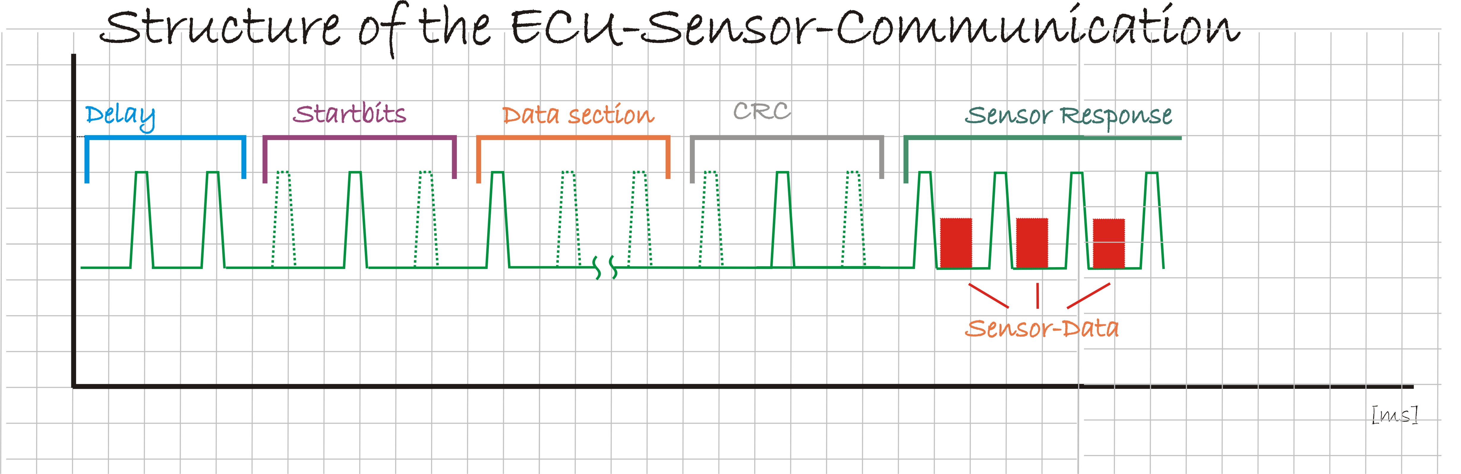
The data format has the following sections
start condition
start bits
data field
error detection
send phase of the sensors after synchronous impulse.
This method can be used by the data format 1 (Short), 2 (Long 4 and 8-Bit data word) and 3 (XLong) and (XXLong).
The data section and the frame is segmented as follows:
The length of the data format is defined by the contents Sensor Adress and the Function Codesl
According to the PSI5-Specifikation the following are bit length results for the different formats:
Format 1 - Short -
15+2 Bit
This data format can be used by Pulse-width-method as well as Tooth-Gap-Method.
Format 2 - Long-
29+3 Bit
This data format can be used by Pulse-width-method as well as Tooth-Gap-Method.
Format 3 - XLong-
37+3 Bit
This data format can be used by Pulse-width-method as well as Tooth-Gap-Method.
Format 4 - XXLong-
43 Bit

This data format can only be used by Pulse-width-method.
You can find a detailed description of PSI5-specifikation on the internet.